Chinese Journal of Applied Chemistry ›› 2025, Vol. 42 ›› Issue (7): 982-992.DOI: 10.19894/j.issn.1000-0518.250215
• Full Papers • Previous Articles Next Articles
Yang LI1, Xing-Wang ZHAO1, Fang DING2( ), Xian WANG3(), Jun-Jie GE3(), Chuan FANG1
Received:2025-05-23
Accepted:2025-06-17
Published:2025-07-01
Online:2025-07-23
Contact:
Fang DING,Xian WANG,Jun-Jie GE
About author:gejunjie@ustc.edu.cnSupported by:CLC Number:
Yang LI, Xing-Wang ZHAO, Fang DING, Xian WANG, Jun-Jie GE, Chuan FANG. Design of the Efficient Active Spray Humidifier for Proton Exchange Membrane Fuel Cells[J]. Chinese Journal of Applied Chemistry, 2025, 42(7): 982-992.
Add to citation manager EndNote|Ris|BibTeX
URL: http://yyhx.ciac.jl.cn/EN/10.19894/j.issn.1000-0518.250215
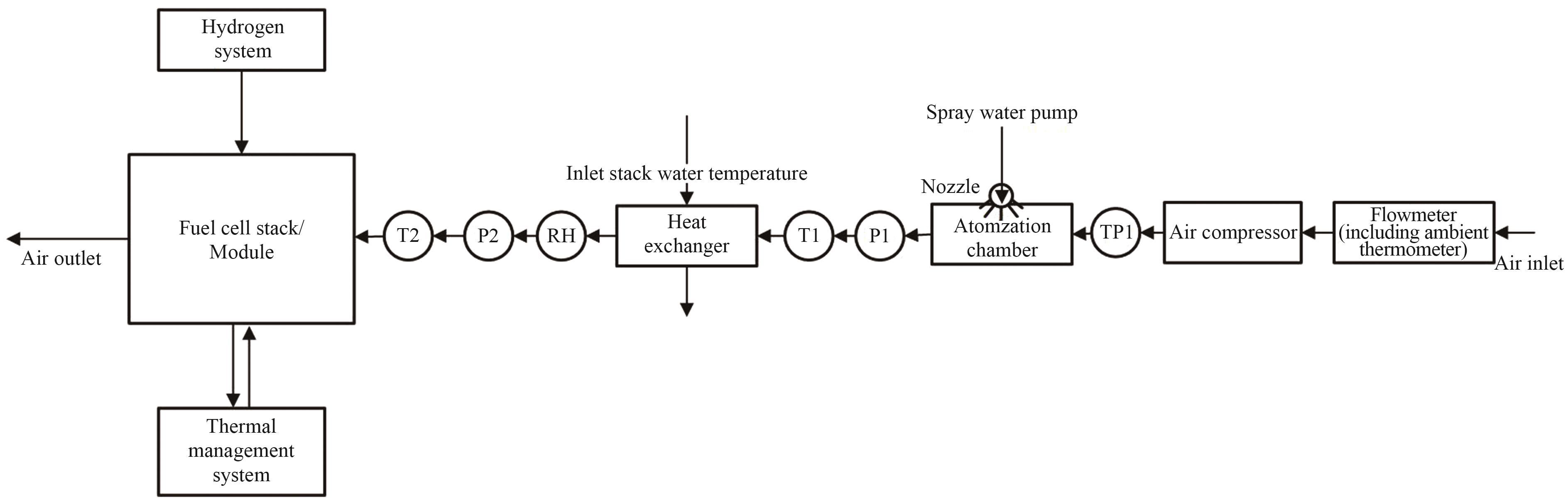
Fig.1 Schematic diagram of the first-generation spray humidification architecture
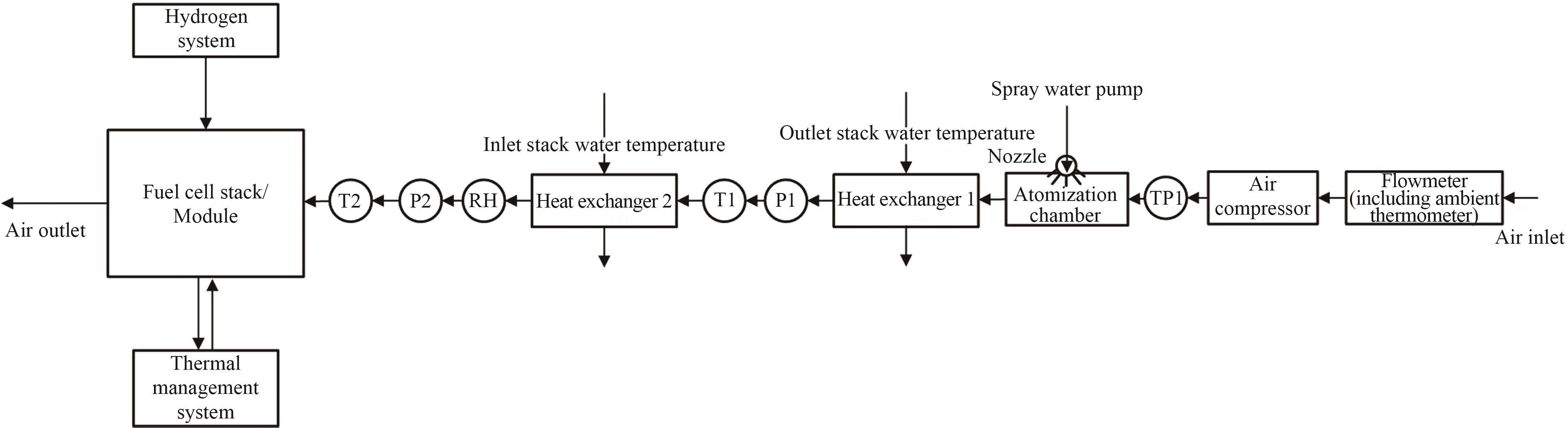
Fig.2 Schematic diagram of the second-generation spray humidification architecture
| j/(mA·cm-2) | ||||||||
|---|---|---|---|---|---|---|---|---|
| 300 | 64 | 33 | 40 | 206.997 1 | -20 | 0.1 | 0.002 9 | 3.45 |
Table 1 Calculation of water volume for spray humidification in the air circuit of fuel cell system
| j/(mA·cm-2) | ||||||||
|---|---|---|---|---|---|---|---|---|
| 300 | 64 | 33 | 40 | 206.997 1 | -20 | 0.1 | 0.002 9 | 3.45 |
| Air flow rate/(g·s-1) | Air temperature into chamber/℃ | Required water volume/(g·s-1) | Nozzle size | Circulating water temperature/℃ |
|---|---|---|---|---|
| 93.4 | 141 | 3.45 | 0.2 mm×6 mm×4 mm | 64 |
Table 2 Simulation input data for atomization chamber
| Air flow rate/(g·s-1) | Air temperature into chamber/℃ | Required water volume/(g·s-1) | Nozzle size | Circulating water temperature/℃ |
|---|---|---|---|---|
| 93.4 | 141 | 3.45 | 0.2 mm×6 mm×4 mm | 64 |
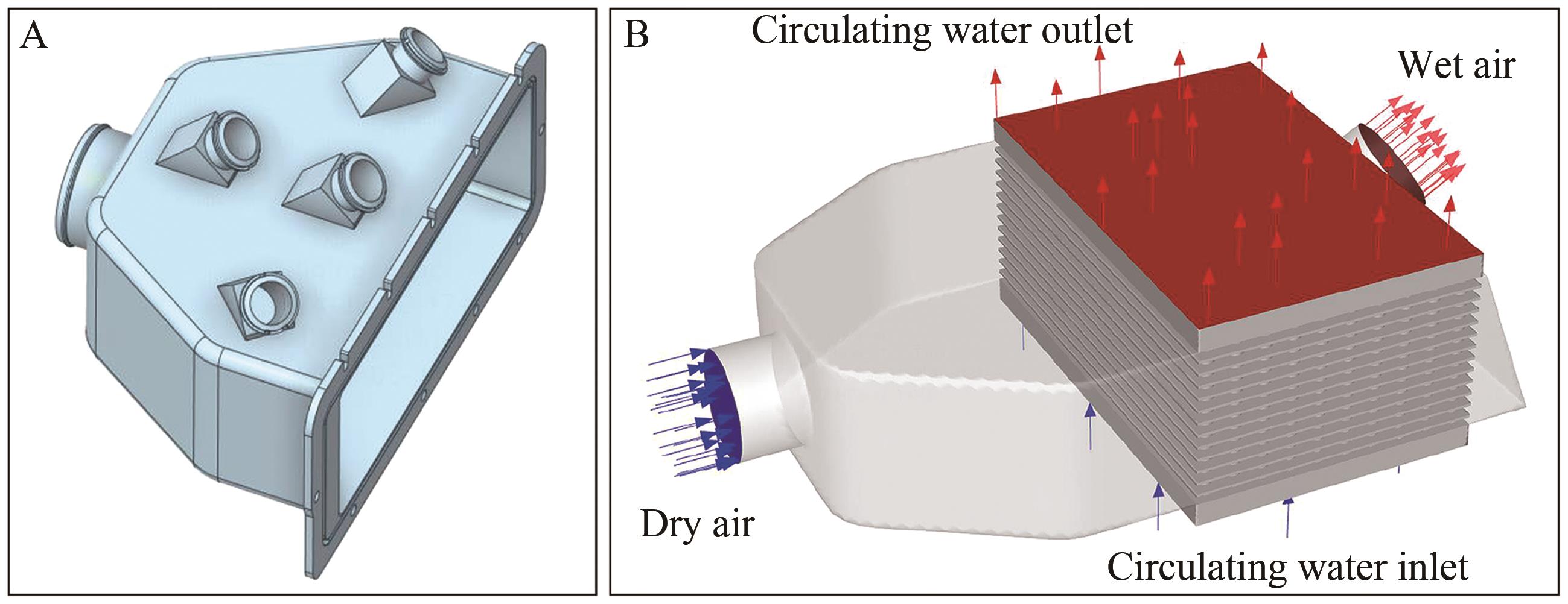
Fig.3 (A) Simulation model of the first-generation atomization chamber and (B) combined simulation model of the first-generation atomization chamber and heat exchanger
| Flow rate error /% | 1 | 2 | 3 | 4 |
|---|---|---|---|---|
| 1st atomization chamber | -12.55 | 12.05 | 11.78 | -11.28 |
| 2nd atomization chamber A | 3.99 | -4.11 | -4.12 | 4.24 |
| 2nd atomization chamber B | -1.01 | 1.02 | 1.15 | -1.16 |
Table 3 Flow rate error comparison of four-zone flow channels between the first-generation atomization chamber and the second-generation A atomization chamber, B atomization chamber
| Flow rate error /% | 1 | 2 | 3 | 4 |
|---|---|---|---|---|
| 1st atomization chamber | -12.55 | 12.05 | 11.78 | -11.28 |
| 2nd atomization chamber A | 3.99 | -4.11 | -4.12 | 4.24 |
| 2nd atomization chamber B | -1.01 | 1.02 | 1.15 | -1.16 |
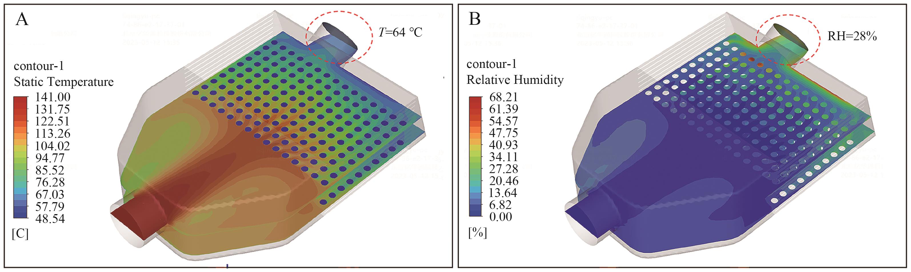
Fig.4 The first-generation atomization chamber (A) Temperature simulation diagram and (B) Humidity simulation diagram
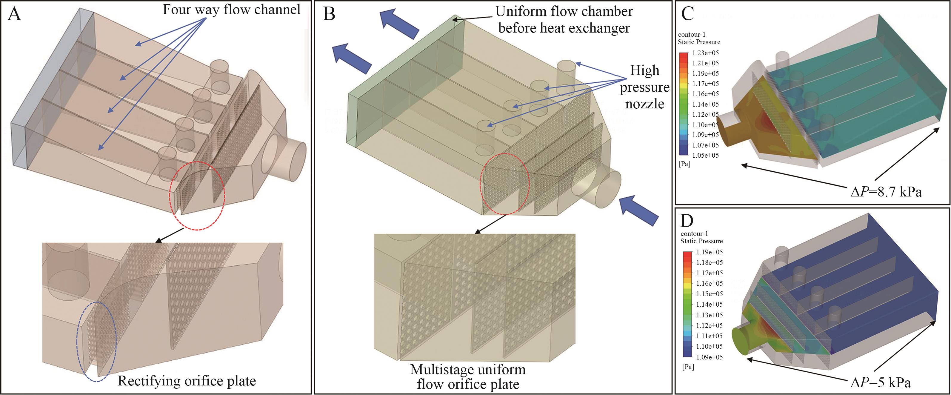
Fig.5 (A) Simulation model of the second-generation atomization chamber A; (B) Simulation model of the second-generation atomization chamber B; (C) Pressure drop of the second-generation atomization chamber A; (D) Pressure drop of the second-generation atomization chamber B
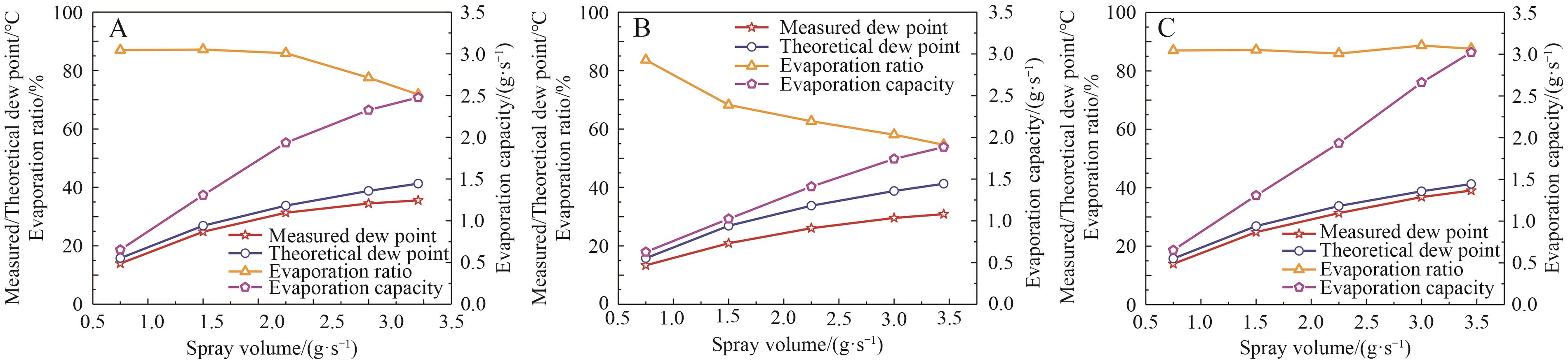
Fig.6 The influence of relative positions of (A) horizontal placement, (B) upward inlet and downward outlet and (C) downward inlet and upward outlet on dew point
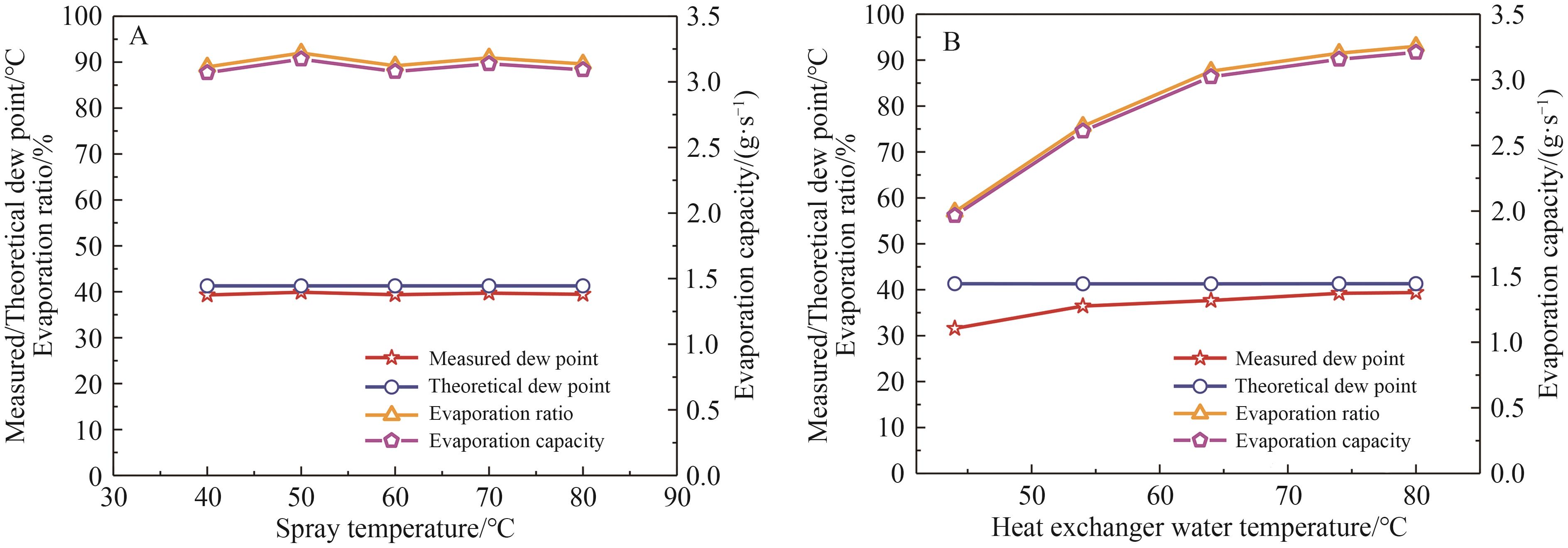
Fig.7 In the downward inlet and upward outlet placement mode, (A) effects of different spray temperatures and (B) effects of different heat exchanger water temperatures on the dew point
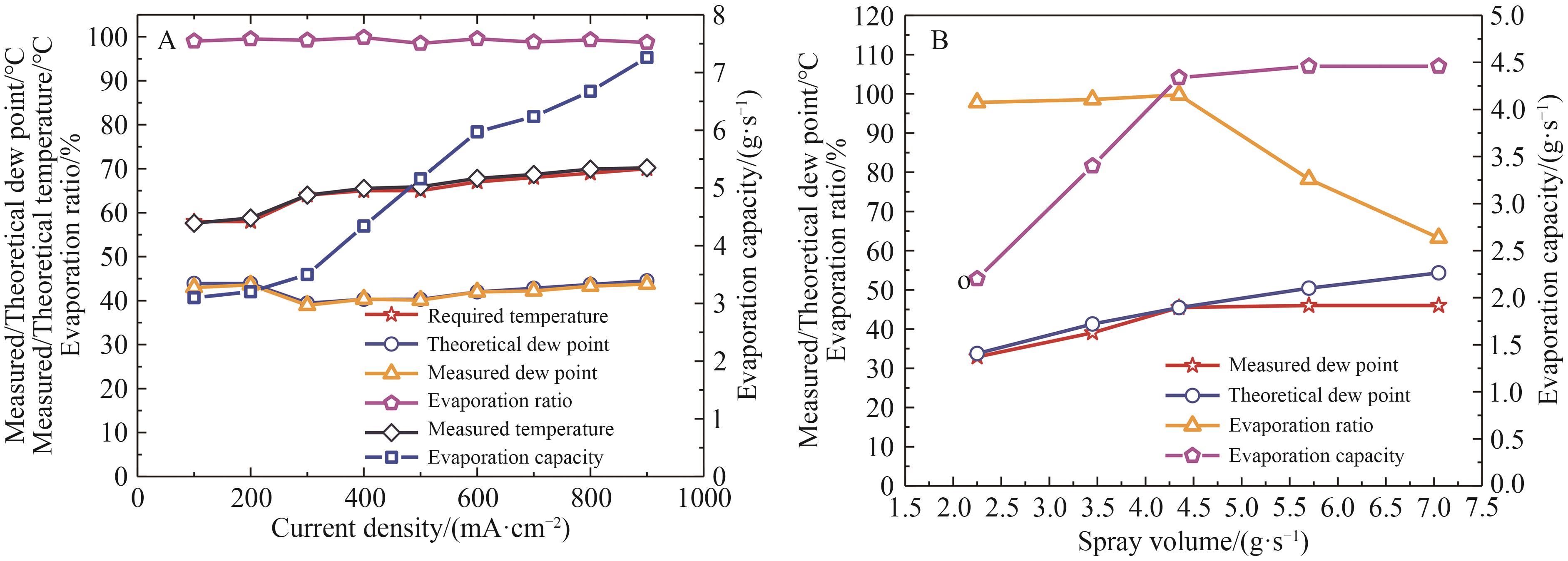
Fig.8 Placement mode of downward inlet and upward outlet for the first-generation atomization chamber + secondary heat exchanger, (A) test data of dew point and evaporation ratio under stack operating conditions and (B) comparison of evaporation ratios under different humidity conditions
| Current density/(mA·cm-2) | Measured dew point/℃ | Theoretical dew point/℃ | Measured temperature/℃ | Theoretical temperature/℃ |
|---|---|---|---|---|
| 100 | 43.00 | 43.91 | 57.60 | 58 |
| 200 | 43.58 | 43.91 | 58.80 | 58 |
| 300 | 38.94 | 39.43 | 64.00 | 64 |
| 400 | 40.35 | 40.28 | 65.50 | 65 |
| 500 | 40.11 | 40.28 | 65.90 | 65 |
| 600 | 41.98 | 41.97 | 67.80 | 67 |
| 700 | 42.23 | 42.82 | 68.70 | 68 |
| 800 | 43.28 | 43.67 | 69.90 | 69 |
| 900 | 43.76 | 44.51 | 70.20 | 70 |
Table 4 Test data of dew point and temperature for spray humidification architecture under stack operating conditions
| Current density/(mA·cm-2) | Measured dew point/℃ | Theoretical dew point/℃ | Measured temperature/℃ | Theoretical temperature/℃ |
|---|---|---|---|---|
| 100 | 43.00 | 43.91 | 57.60 | 58 |
| 200 | 43.58 | 43.91 | 58.80 | 58 |
| 300 | 38.94 | 39.43 | 64.00 | 64 |
| 400 | 40.35 | 40.28 | 65.50 | 65 |
| 500 | 40.11 | 40.28 | 65.90 | 65 |
| 600 | 41.98 | 41.97 | 67.80 | 67 |
| 700 | 42.23 | 42.82 | 68.70 | 68 |
| 800 | 43.28 | 43.67 | 69.90 | 69 |
| 900 | 43.76 | 44.51 | 70.20 | 70 |
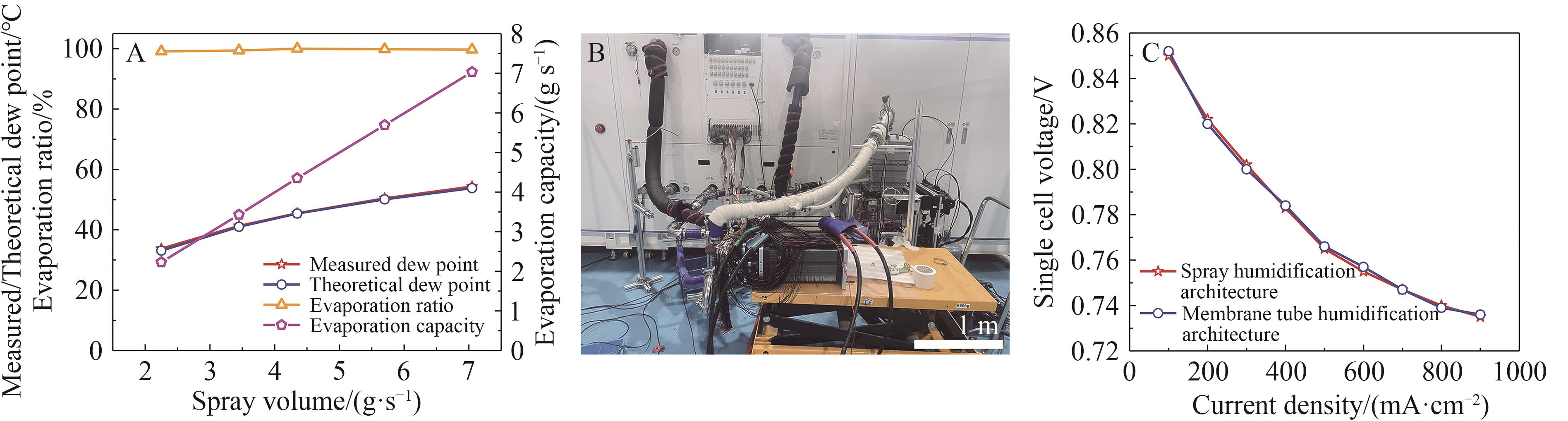
Fig.9 Placement mode of downward inlet and upward outlet for the second-generation atomization chamber + secondary heat exchanger. (A) Changes in dew point and evaporation ratio under different humidity conditions; (B) Photos of the joint debugging of the spray humidification architecture and the stack; (C) Comparison of polarization curves during the joint debugging of the spray humidification architecture and the stack
| Current density/(mA·cm-2) | Performance (V) of single cell in the stack with spray humidification architecture | Performance (V) of a single cell in the stack with membrane tube humidification architecture |
|---|---|---|
| 100 | 0.850 | 0.852 |
| 200 | 0.822 | 0.820 |
| 300 | 0.802 | 0.800 |
| 400 | 0.783 | 0.784 |
| 500 | 0.765 | 0.766 |
| 600 | 0.755 | 0.757 |
| 700 | 0.747 | 0.747 |
| 800 | 0.740 | 0.739 |
| 900 | 0.735 | 0.736 |
Table 5 Performance comparison of the stack with spray humidification architecture and membrane tube humidification architecture
| Current density/(mA·cm-2) | Performance (V) of single cell in the stack with spray humidification architecture | Performance (V) of a single cell in the stack with membrane tube humidification architecture |
|---|---|---|
| 100 | 0.850 | 0.852 |
| 200 | 0.822 | 0.820 |
| 300 | 0.802 | 0.800 |
| 400 | 0.783 | 0.784 |
| 500 | 0.765 | 0.766 |
| 600 | 0.755 | 0.757 |
| 700 | 0.747 | 0.747 |
| 800 | 0.740 | 0.739 |
| 900 | 0.735 | 0.736 |
| [1] | WANG Y, RUI Z D, CHEN K, et al. Materials, technological status, and fundamentals of PEM fuel cells-a review[J]. Mater Today, 2020, 32: 178-203. |
| [2] | JIAO K, LI X. Water transport in polymer electrolyte membrane fuel cells[J]. Prog Energy Combust Sci, 2011, 37(3): 221-291. |
| [3] | ZHANG G, KANDLIKAR S. A critical review of cooling techniques in proton exchange membrane fuel cell stacks[J]. Int J Hydrogen Energy, 2012, 37(3): 2412-2429. |
| [4] | CHANG Y, QIN Y, YIN Y, et al. Humidification strategy for polymer electrolyte membrane fuel cells-a review[J]. Appl Energy, 2018, 230: 643-662. |
| [5] | CASALEGNO A, ANTONELLIS S, COLOMBO L, et al. Design of an innovative enthalpy wheel based humidification system for polymer electrolyte fuel cell[J]. Int J Hydrogen Energy, 2011, 36(8): 5000-5009. |
| [6] | FU P, LAN Z, CHENY, et al. A review on modeling methods and key parameters control of proton exchange membrane fuel cell based on numerical comparison[J]. Energy Convers Manage, 2025, 324: 119309. |
| [7] | CHOWDURY M, PARK Y, PARK S, et al. Degradation mechanisms, long-term durability challenges, and mitigation methods for proton exchange membranes and membrane electrode assemblies with Pt/C electrocatalysts in low-temperature and high-temperature fuel cells: a comprehensive review[J]. J Electroanal Chem, 2024, 975: 118712. |
| [8] | KAMAL M, JAAFAR J, KHAN A, et al. A critical review of the advancement approach and strategy in speek-based polymer electrolyte membrane for hydrogen fuel cell application[J]. Energy Fuels, 2024, 38(14): 12337-12386. |
| [9] | KISHORE S, PERUMAL S, ATCHUDAN R, et al. A critical review on artificial intelligence for fuel cell diagnosis[J]. Catal, 2022, 12(7): 743. |
| [10] | ZHANG T, WANG P, CHEN H, et al. A review of automotive proton exchange membrane fuel cell degradation under start-stop operating condition[J]. Appl Energy, 2018, 223: 249-262. |
| [11] | AINDOW T, O'NEILL J. Use of mechanical tests to predict durability of polymer fuel cell membranes under humidity cycling[J]. J Power Sources, 2011, 196(8): 3851-3854. |
| [12] | WANG L, HUSAR A, ZHOU T, et al. A parametric study of PEM fuel cell performances[J]. Int J Hydrogen Energy, 2003, 28(11): 1263-1272. |
| [13] | ZHOU S, FAN L, ZHANG G, et al. A review on proton exchange membrane multi-stack fuel cell systems: architecture, performance, and power management[J]. Appl Energy, 2022, 310: 118555. |
| [14] | FANG M, WAN X, ZOU J. Development of a fuel cell humidification system and dynamic control of humidity[J]. Int J Energy Res, 2022, 46(15): 22421-22438. |
| [15] | FANG M, ZOU J,YIN C, et al. Prediction and parametric analysis of bubble humidifier performance in a polymer electrolyte membrane fuel cell test system by response surface methodology[J]. Energy Sources Part A, 2022, 44(2): 3497-3508. |
| [16] | EDER E, HILLER S, BRUEGGEMANN D, et al.Characteristics of air-liquid heat and mass transfer in a bubble column humidifier[J]. Appl Therm Eng, 2022, 209: 118240. |
| [17] | D'ADAMO A, MARTOCCIA L, CROCI F, et al. CFD simulation of the effect of membrane thickness and reactants flow rate on water management in PEM fuel cells[J]. Int J Heat Mass Tran, 2025, 249: 127207. |
| [18] | POLLAK M, TEGETHOFF W, KOEHLER J. Analysis of the effects of fiber positioning on water transfer in hollow fiber humidifiers using CFD and statistical uniformity metrics[J]. Heat Mass Transfer, 2025, 61(10): 1. |
| [19] | GUO Z, CHEN H, GUO H, et al. Study on two-phase transport and performance characterization in orientational structure proton exchange membrane fuel cells at high water content[J]. Appl Energy, 2025, 392: 125970. |
| [20] | WOOD D, YI Y, NGUYEN T. Effect of direct liquid water injection and interdigitated flow field on the performance of proton exchange membrane fuel cells[J]. Electrochim Acta, 1998, 43(24): 3795-3809. |
| [21] | NGUYEN T, WHITE R. A water and heat management model for proton-exchange-membrane fuel-cells[J]. J Electrochem Soc, 1993, 140(8): 2178-2186. |
| [22] | JUNG S, KIM S, KIM M, et al. Experimental study of gas humidification with injectors for automotive PEM fuel cell systems[J]. J Power Sources, 2007, 170(2): 324-333. |
| [23] | SUNG C, BAI C, CHEN J, et al. Controllable fuel cell humidification by ultrasonic atomization[J]. J Power Sources, 2013, 239: 151-156. |
| [24] | VERHAGE A, COOLEGEM J, MULDER M, et al. 30,000 h operation of a 70 kW stationary PEM fuel cell system using hydrogen from a chlorine factory[J]. Int J Hydrogen Energy, 2013, 28(11): 4714-4724. |
| [25] | ZHANG H, QIAN Z, YANG D, et al. Design of an air humidifier for a 5 kW proton exchange membrane fuel cell stack operated at elevated temperatures[J]. Int J Hydrogen Energy, 2013, 38: 12353-12362. |
| [26] | HU H, XU J, ZHANG H, et al. CFD investigation of a fast-response humidifier for high-power PEMFC test stations[J]. Int J Hydrogen Energy, 2024, 52: 1056-1069. |
| [1] | Yi-Ning DONG, He LI, Xue GONG, Ce HAN, Ping SONG, Wei-Lin XU. Research Progress of Non-Pt-Based Catalysts in Cathode Oxygen Reduction Reaction of Proton Exchange Membrane Fuel Cells [J]. Chinese Journal of Applied Chemistry, 2023, 40(8): 1077-1093. |
| [2] | FU Fengyan,CHENG Jingquan. Progress in Applications of Electrospun Nanofibers as Proton Exchange Membrane in Fuel Cells [J]. Chinese Journal of Applied Chemistry, 2020, 37(4): 405-415. |
| [3] | MA Juan1,3, SUI Qi2, LU Tianhong2*. Complexing Self-reduction Synthesis of Silver Nanoparticles and Their Electrocatalytic Performance [J]. Chinese Journal of Applied Chemistry, 2014, 31(11): 1330-1335. |
| [4] | YANG Yong, ZHAO Wenwen, SHI Qingle, ZHANG Hua*. Preparation of Pt-HxWO3 Anodes by Electrochemical Reduction [J]. Chinese Journal of Applied Chemistry, 2011, 28(12): 1408-1414. |
| [5] | WANG Yan-En1, CAO Shuang2, TANG Ya-Wen3, WANG Chun1, MA Jing-Jun1, LU Tian-Hong3*. Electrocatalytic Performance of Carbon-Supported Pt-P Catalyst for Oxygen Reduction [J]. Chinese Journal of Applied Chemistry, 2011, 28(01): 44-47. |
| Viewed | ||||||
|
Full text |
|
|||||
|
Abstract |
|
|||||